There have been questions about how to design flexible strip led lights, so I thought I would share my experience.
The first decision I had to make was to use either Constant Current (CC) or Constant Voltage (CV) flexible led strips.
There are arguments about efficiencies regarding CV and CC. The CV strips achieve constant current flow by using resistors to balance the current draw of each section. We will discuss sections later. Using resistors to balance current flow wastes current on the resistors. The CC strips maintain current flow using a transistor. The transistor does not waste current flow.
I have used both CC and CV strips. A Cv strip needs a Constant Voltage 12v or 24v depending on your forward voltage, which we also discuss later. Just know for now, 24v forward voltage is better than 12v forward voltage.
I will be discussing CC flexible strips here only.
The first choice is what diode to use. I use the Samsung LM561C diode. You can choose what Kelvin you prefer or you can get mixed spectrum. I used 5000k and 3000k for my choices.
The second choice is how many leds in a meter are you looking for. Normally, 60 to 70 leds/m is industry standard. The Samsung LM561C is the best choice for lm/w as well when looking athow many diodes per meter. My strips have 70 diodes per meter.
The third choice is to decide what type of LED driver to use. You can use most any MeanWell 185H style driver that delivers 200w total power. In that roup you have many choices from a C350B to a C1400B. The lower the amperage the more forward voltage available. I have some extra C1400B drivers laying around from some COB builds in the past so I am going to use those for my example.
Now that we have chosen, CC flexible strips with 60-70leds/m and a MW HLG-185H-C1400B driver we can now discuss specifics.
First, let’s look at amperage.
The C1400B driver has 1400mA of Constant Current. For our uses we only need 88mA per diode per Samsung to get 200lm/w output from each diode we use. So how we do we get just 88mA from a 1400mA driver? We can use basic electric circuit knowledge, amps add up in parallel connections, and volts add up in series connections.
Our first piece of math is to divide 1400ma/88ma and we get 15.9. Let’s go with 16 as a number for whole numbers. We need 16 rows connected in parallel, because current adds in parallel. So our first decision is we need 16 rows. Rows of what, you are probably thinking, which is good.
Our second piece of math is to decide what will a row consist of. Volts are additive so now we will look at how many volts we want to use. The MW C1400B driver has a max Forward Voltage Vf of 143v. By using 183v we will get the maximum wattage out of the driver, in this case 200w.
How do we choose out voltage?
First we shall look at the flexible strips. I am using flexible Samsung LM561C strips by Mofue Technology Ltd, Roget Zheng. https://mufue.en.alibaba.com/?spm=a2700.8443308.0.0.AQm70S
My strips have 70 diodes per meter. To make things workable, my strip[s have 7 diodes per cut section. Each diode has a Vf of 2.7-2.9v. China has access to the lower two bins, 2.9vf and 2.8vf, while us has access to 2.7vf. For my purposes, I have 2.8 bin. Math time again 7 x 2.8 = 19.6vf for a single section. Now some more math divide 143/19.6 = 7.2. We can use 7 sections.
Each flexible strip on the reel is one long series connection.
I cut my strip into a section 7 segments long. My segments measured 27” in total length each. I am using 16 rows in my design to get that 88mA drive current I want, so I am cutting 16 sections from my reel ion seven segment lengths.
When I lay out my rows, they are all equal length and all the positive are facing the same direction. Positive on right, negative on left marked on the strips. Now I can either solder red wire for positive, and black wire for negative. I am using 22 gauge wire If you do not want to solder, you can purchase the strip connectors, as well online. I would need sixteen connectors for this project., or solder 32 wires on the strips individually. I chose to solder.
Strip connectors – https://www.ebay.com/i/202018474015?chn=ps&dispctrl=1
The strips are not that difficult to solder but they take patience and practice. If you are not that good at soldering, get the connectors and make it a solderless project.
Parallel connections.
Now that I have positive and negative identified, red positive, black negative, I am going to connect all the positive wires together and all the negative wires together.
You can use wagos, or other connectors, here as well.
Group the bundles into fours and have one wire to the next wago, to make them all connected in parallel. I soldered mine together, first into groups of fours, and connected those into a single positive and negative, and placed a spade connector on each, for connecting to the LED drivers positive and negative.
Connect Positive to V+ and negative to V- on the MeanWell driver.
You can use a wago to connect the positive to the positive to your drivers positive, and the negative to your drivers negative..
Now connect a 10k dimmer, Dim+ to the center of the dimmer, and Dim- to the outside, left looking from bottom with a 10k resistor connected in series between the driver and the dimmer.
Now that is all dc connections are complete you can connect your ac plug to the business end of your driver.
You can use any three prong plug for this purpose.
https://www.ebay.com/p/Cooper-Wiring-SA399-Grounded-Cord-Plug-Black/691352377?iid=253220125659
https://www.itead.cc/smart-home/sonoff-th.html
I used a Sonoff TH10 it also provide temperature and humidity data and just plug the wires into the L-load, N-Neutral, and E-earth or Ground. All you need to remember is the wide spade connector on your outlet is the neutral side of the plug. Ground is center and Load is the smaller plug. The Sonoff device needs a plug connected to it to plug into a 110v outlet, or plug your driver into the outlet.
Plug your new strip light in.
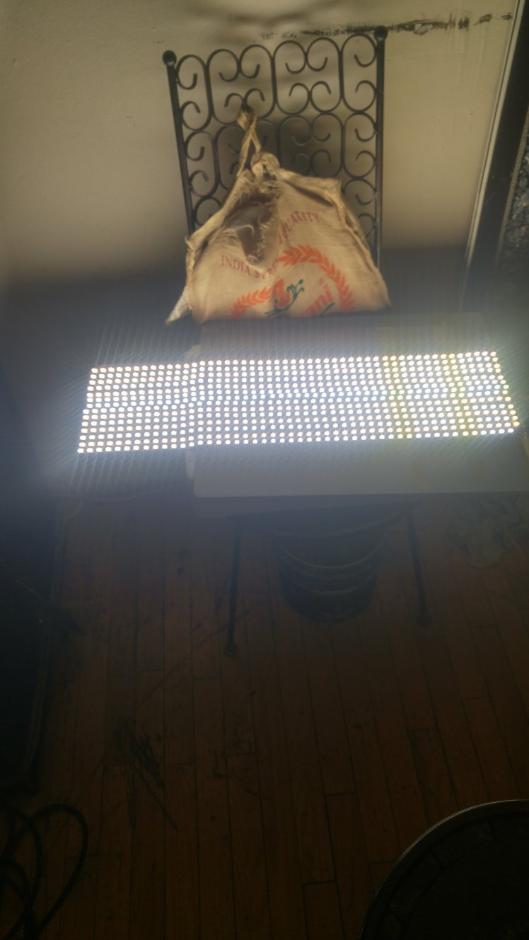
The fixture should light up. If not check your connections and ensure they are solid. If the connections are solid your new light will illuminate. You can use the dimmer to test your lights capabilities.. You should have about 200 PAR at 6” and 130 PAR at 12”. Not bad for a DIY trip light. I found that I can make two of these fixtures from 20m of leds. I bought 3000k and 5000k 20m each and another 10m of 5000k for extras.
Enjoy your DIY flexible strip projects. I did.

search engine optimation
LikeLike